News
Design Considerations for Primary vs Secondary GIS
Medium-voltage Gas-Insulated Switchgear (GIS) is used across a wide range of applications: from compact secondary substations in urban areas to large, complex primary substations feeding industrial plants and high-capacity distribution networks.
Although both “primary GIS” and “secondary GIS” operate at similar voltage levels (typically 12–36 kV), their design philosophies, performance requirements, protection schemes, and mechanical layouts differ substantially. Understanding these differences helps EPCs, DSOs, and industrial operators select the right technology — especially as the market shifts towards SF₆-free GIS alternatives.
This article explains the key design considerations for primary vs secondary GIS and highlights how modern SF₆-free GIS addresses the requirements of both segments.
1. What Is Secondary GIS?
Secondary GIS is typically used in secondary distribution networks, where loads are smaller, protection schemes are simpler, and switching operations are infrequent.
Typical characteristics of secondary GIS:
- Operating voltages: 12–24 kV (sometimes 36 kV)
- Low rated currents: 400 / 630 A
- Short-circuit levels: 16 kA even lower
- Applications:
- Ring Main Units (RMUs)
- Distribution substations in urban/rural grids
- Rooftop or basement substations
- Commercial buildings
- Small renewable plants
- Switching frequency: low
- Functional units: simple feeder panels, load-break switches, fuse protection
Secondary GIS prioritizes compactness, simplicity, affordability, and ease of installation.
2. What Is Primary GIS?
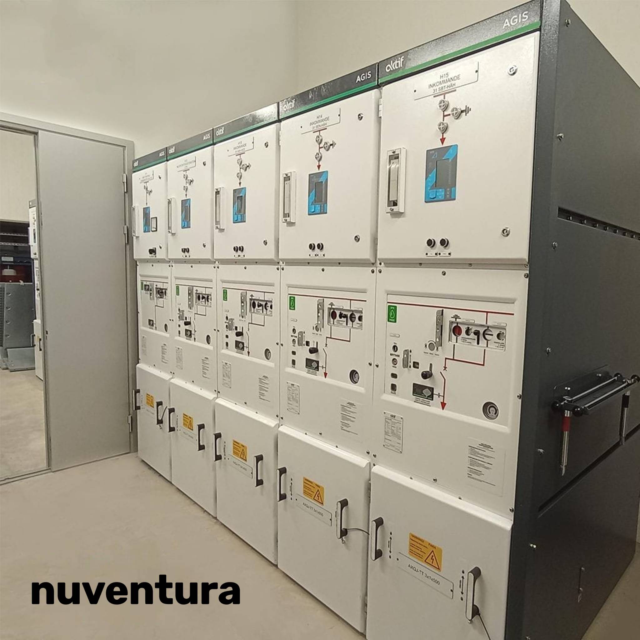
Primary GIS is installed at primary substations, where MV networks interface with transmission grids or large-scale industrial infrastructure.
Typical characteristics of primary GIS:
- Operating voltages: 24–36 kV
- Rated currents: 1250 A up to 2000 A and more
- Short-circuit levels: 25–31.5 kA and more
- Applications:
- Large utility primary substations
- Industrial plants (steel, chemical, automotive)
- Data centres
- Utility-scale wind/solar substation
- Switching frequency: medium to high
- Functional units:
- Circuit breakers
- PT/CT measurement bays
- Busbar sectionalizers
- Earthing switches
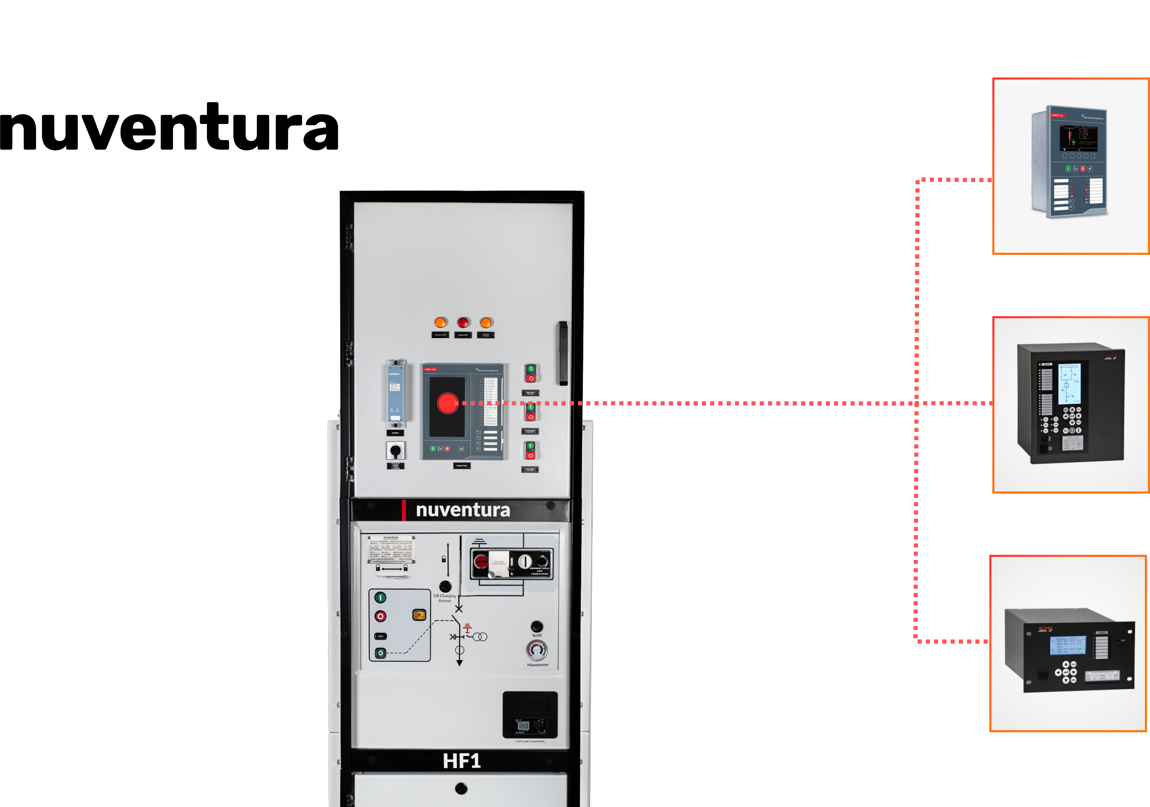
- Protection relays (distance, differential, feeder protection)
Primary GIS prioritizes performance, reliability, protection capability, and safe maintainability.
3. Key Design Differences Between Primary and Secondary GIS
3.1 Switching & Interruption Technology
Secondary GIS
- Often uses load-break switches
- Fuse-switch combinations are common
- Circuit breakers may be optional
Primary GIS
- Relies heavily on full circuit breakers
- Must interrupt higher short-circuit currents
- Requires stronger mechanical components
- Current transformers and protection relays act in combination with the circuit breakers
This determines the thermal and mechanical sizing of busbars, contacts, and enclosure strength.
3.2 Protection Philosophy
Secondary GIS
- Protection is simpler:
- Fuses
- Basic overcurrent protection
- Limited interlocking logic
Primary GIS
- Advanced protection schemes:
- Differential protection
- Distance protection
- Directional overcurrent
- Busbar protection
- Automatic transfer systems (ATS)
This impacts CT/VT arrangements, panel depth, cable compartments, and relay room interfaces.
3.3 Compartmentalization and Safety Requirements
Secondary GIS
- Often shared compartments
- Internal Arc Classification (IAC) usually AFL
- Pressure relief is smaller in scale
Primary GIS
- Strict separation of:
- Cable compartment
- Breaker compartment
- Busbar compartment
- VT/CT compartment
- IAC requirements typically AFLR at 25–31.5 kA / 1s
- Larger and more complex pressure-relief ducts
Higher arc-fault currents require a more robust mechanical design.
3.4 Busbar Systems and Expandability
Secondary GIS
- Single busbar
- Limited options for future expansion
- Compact and modular for space-constrained installations
Primary GIS
- Offers:
- Single or double busbar options
- Bus sectionalizers
- Larger cable bays
- Flexible future expandability
3.5 Maintenance & Accessibility
Secondary GIS
- Typically “sealed for life”
- Minimal maintenance
- Designed for non-specialist technicians
Primary GIS
- “Sealed for life” but not completely welded (facility to repair)
- Requires access for:
- CT/VT maintenance
- Relay testing
- Arc protection systems
- Must allow multiple maintenance conditions (de-energized, earthed, isolated)
This affects panel dimensions, doors, interlocking, and safety protocols.
4. How SF₆-Free GIS fits into Primary vs Secondary Requirements
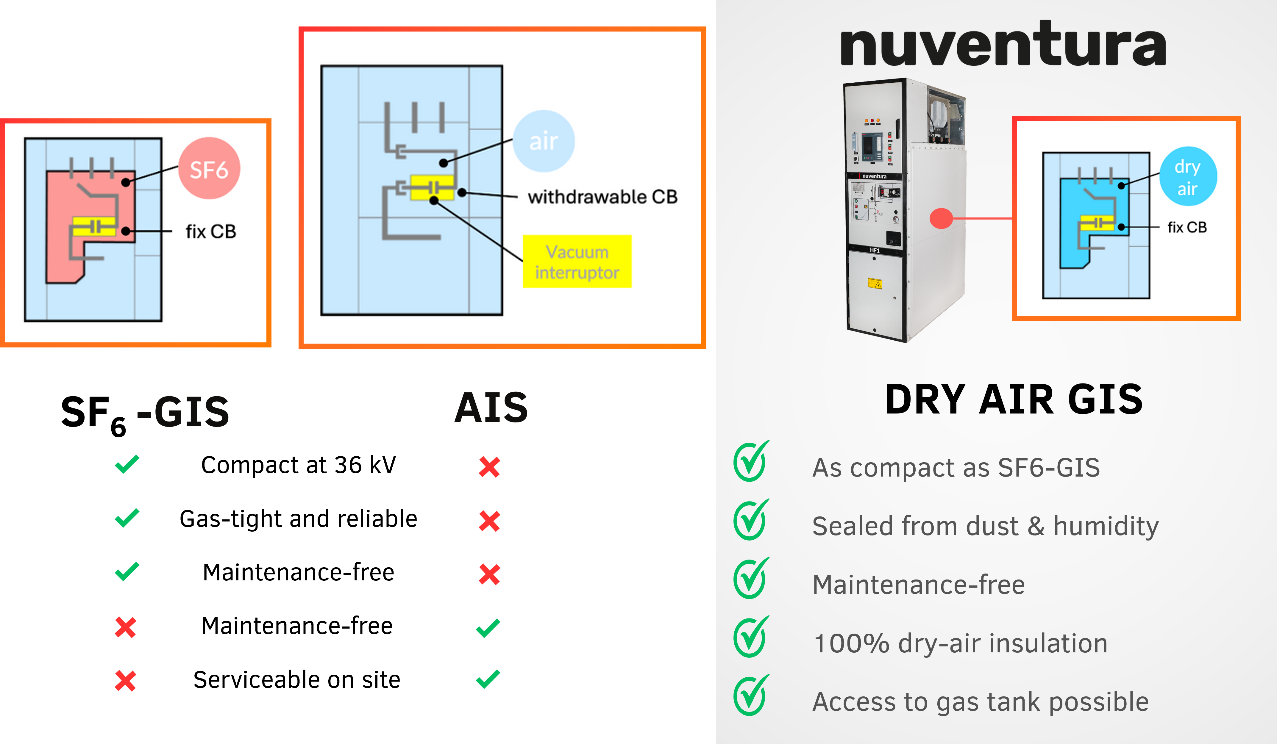
Modern SF₆-free GIS using dry air insulation can serve both segments effectively, but design strategies differ.
4.1 In Secondary Applications
SF₆-free GIS offers:
- Similar compactness to SF₆-RMU
- No SF₆ decomposition by-products
- Lower OPEX, simpler service model
This is ideal for utilities looking to decarbonize large installed bases of secondary substations.
4.2 In Primary Applications
Primary GIS imposes more demanding requirements — but SF₆-free technologies have now matured enough to meet them.
Key advantages:
- Achieves IAC AFLR 25–31.5 kA performance with robust mechanical design
- No toxic by-products during arcs
- Easier end-of-life processes (no gas reclamation)
- Attractive for data centres, industry, and large utilities with strict ESG goals
Primary GIS is where the carbon and safety advantages of SF₆-free insulation become most valuable.
5. What Buyers Should Consider When Choosing Between Primary & Secondary GIS
Technical criteria:
- Fault level (16/25/31.5 kA)
- Rated currents
- Number of feeders and switching frequency
- Grid topology (single or double busbar)
- Protection relay requirements
- IAC classification
- Cable termination sizes
- CT/VT measurement needs
Operational criteria:
- Maintenance philosophy
- Operator competence
- Expected grid expansions
- Remote control and SCADA requirements
Sustainability & compliance:
- Upcoming regulatory restrictions (EU F-Gas 2024/573)
- Avoidance of SF₆ handling
- Corporate net-zero policies
6. Conclusion
Primary and secondary GIS share a common purpose — safe and reliable MV distribution — but their design priorities differ fundamentally. Secondary GIS focuses on compactness and simplicity, whereas primary GIS emphasizes switching performance, arc safety, and flexible grid operation.
With the growing shift toward SF₆-free technology, both primary and secondary applications now have modern, sustainable alternatives that meet or exceed the performance of legacy SF₆ equipment. Whether in compact city substations or high-demand industrial facilities, SF₆-free GIS supports safer operation, lower environmental impact, and future-ready grid design.
Stay informed and inspired
You can also stay informed and inspired by subscribing to our quarterly newsletter

More News
.png)


Nuventura joins Lucy Electric to accelerate global adoption of SF₆-free primary switchgear
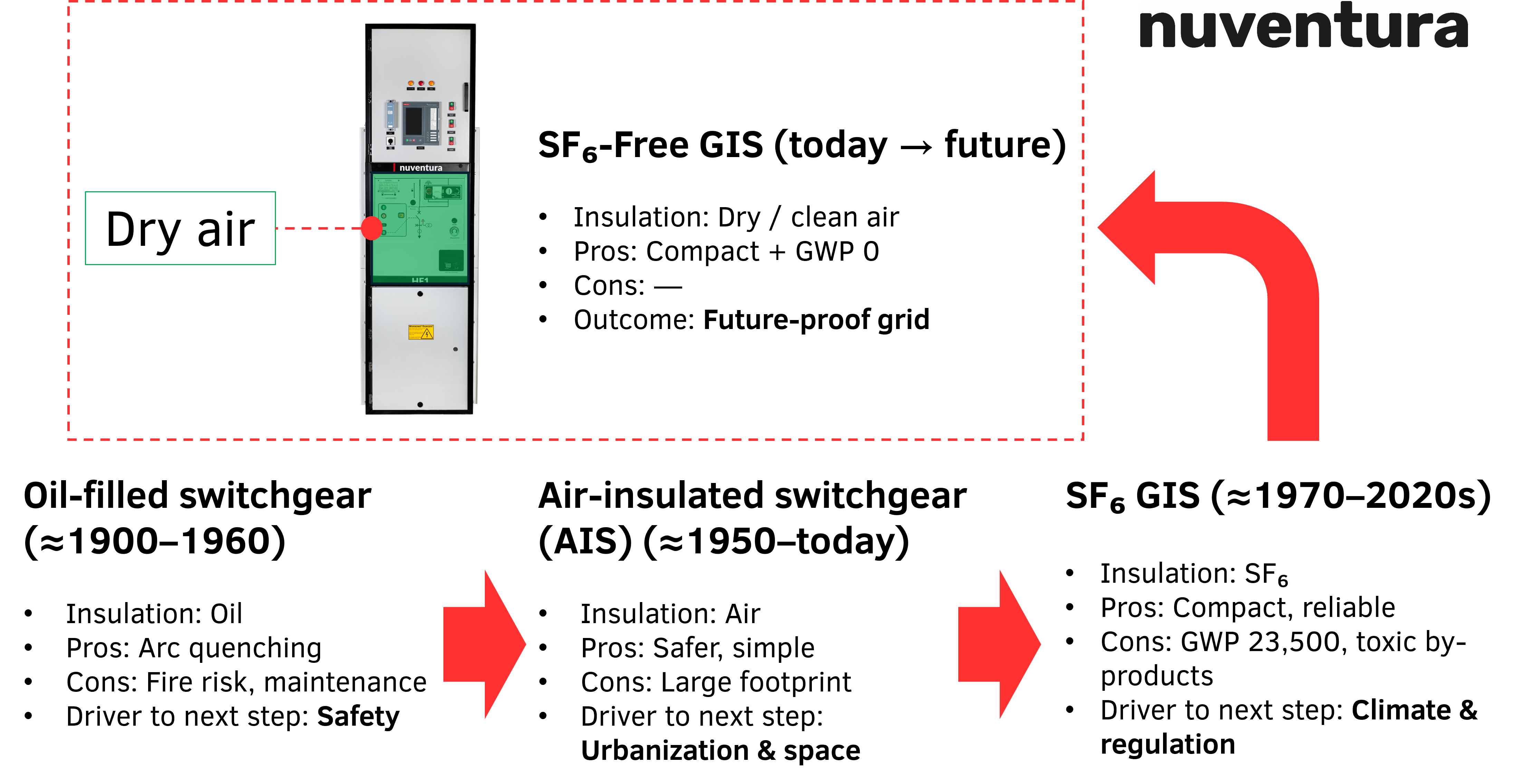
The Evolution of MV Switchgear: From Oil → AIS → SF₆ → SF₆-Free GIS
The Carbon Footprint of SF₆ vs SF₆-Free Switchgear
What Utilities Must Consider in Tender Specifications for SF₆-Free GIS
.png)
How Switchgear Type-Testing Works – The IEC 62271-200 Journey
_sz3.jpg)
Partial Discharge in MV Switchgear — Causes, Detection, and Prevention
.png)
Design Considerations for Primary vs Secondary GIS
Internal Arc Classification Explained (IAC AFLR, 16/25/31.5 kA Basics)
Environmental Advantages and Potential Carbon Credits to SF6-free Switchgear in the Indian Context
Explanation of the relay protection functions required in MV grids
AIS vs GIS — Combining the Best of Both Worlds with SF₆-Free Technology
Why Voltage Levels Matter in Medium-Voltage Grids
Protection Relays – The Intelligence Behind Medium-Voltage Switchgear
Raising the Bar for Switchgear Safety
Nuventura and Elgór and Hansen enter partnership to bring SF₆-free switchgear to Poland

Nuventura and WESCOSA join forces to bring F-Gas-free GIS to the Middle East

CO7 and Nuventura announce partnership

Nuventura and PMS join forces for a greener future in power solutions

Introducing Nuventura’s ESG function and Cassidy Kuiper
Connect with our experts
Whether it’s SF₆-free switchgear specifications, partnership opportunities or support – our team is ready to answer your questions and find the right eco-friendly solution for your needs.
Do you have a specific request?
Get in touch